
Has anyone here changed the Biqu B1 SKR v1.4 mainboard to SKR MINI E3 V3?
You must log in or register to comment.
Well. Why would you want to do that?
In the end, choose the board that has the features you need. Software is the same anyway.
With Klipper you can even combine multiple boards to get the features you want.
Suspected that the SKR v1.4 original motherboard died (Hotend not heating), so advanced to the SKR MINI v3 + a Raspberry PI for Klipper.
I’m looking for “printer.cfg” that matches this setup…The printer.cfg is highly dependent on your setup. For reference you can look at the example config for the SKR mini e3 v3: https://github.com/Klipper3d/klipper/blob/master/config/generic-bigtreetech-skr-mini-e3-v3.0.cfg
Thanks. I’ve already used this one.
In the config file, some pins are named like “PB0”, but other have a “!” in front, like “!PB1”, and other a “^”, like “^PC2”. What are the “!” and “^” for?
What’s the difference between a “PB0” and a “PC11”.An exclamation mark (!) inverts a pin. The other symbol (^) enables a pull up resistor on a pin, which is needed for things like endstops or buttons. These can also be combined.
PB0 is just the name of one pin. PC0 would be a completely different pin.
Different Microcontrollers have different naming conventions, that is why you sometimes see names like PB10 and on other controllers it might be GPIO10.
See also the documentation: https://www.klipper3d.org/Config_Reference.html
Thank you! This helped a lot.
Now, in the pinout for my old SKR v1.4 FAN0 is"12/24v" and "2.3", while FAN1 is"GND" and "12/24v".
What are the difference between FAN0 and FAN1 port on the motherboard?(I’ve had a working 3D printer for 6 days, and have no experience with anything 3D printing related, so therefore these noob questions. )
Glad to be of help!
The FAN1 in this case can not be controlled by software. It will always be on as soon as the printer is powered.
Here comes the fun part.
The Biqu B1 has all it’s wires to the hotend via a USB-C cable. All wires from the motherboard goes to a card in the back of the printer, and fom there is a USB-C to a card in the hotend. This card splits up to TH0, CNCFAN, CNCAN1, FAN2 and HE0. Even power to the nozzle heater goes in the USB-C.On the old SKR v1.4, the wire labeled DCIN were connected to FAN1 (GND - 12/24v), and FAN0 were connected to FAN0 (2.3 - 12/24v).
On the new SKR MINI V3 the DCIN wire is connected to FAN1 (12/24v - PC7), and FAN0 wire to FAN0 (12/24v - PC6).
The wire DCIN is not from PSU, but gives power to the card in the hotend.In the printer.cfg all of fan-stuff are commented out, and the only thing is:
[fan_generic hotend_fan] #use for testing of hotend fan pin: PC7
pin: PC7

[fan] #part fan pin: PC6
Pin: PC6
This gives me sliders in Klipper for PC6 and PC7, and I can set FAN1 to 100%.
This should in (my) theory give power to the card in the hotend. But when i slide FAN0 in Klipper nothing happens with the fans.
When i disconnect the wires to the nozzle heater from the motherboard i now have about 24 volts on those wires, and this happens without heating the heater.
The reason for me starting this project was that one day i just got error message when heating the nozzle. First i bought a new heater, thermistor and the block they are mounted in. This did not help. So, now the motherboard is replaced and I’ve added a Raspberry PI with Klipper to the setup, and still no joy.
Looking closer on the X, Y, Z and E ports i observe that the ports are labeled different on the two cards.
Old SKR v1.4: Square pin = 1B, next pin = 1A, next = 2A, and last is 2B. Also the order is EN | STOP | DIR
New SKR MINI: Square pin = 2B, next pin = 1B, next = 1A, and last is 2A. The order looks like EN | STOP | DIR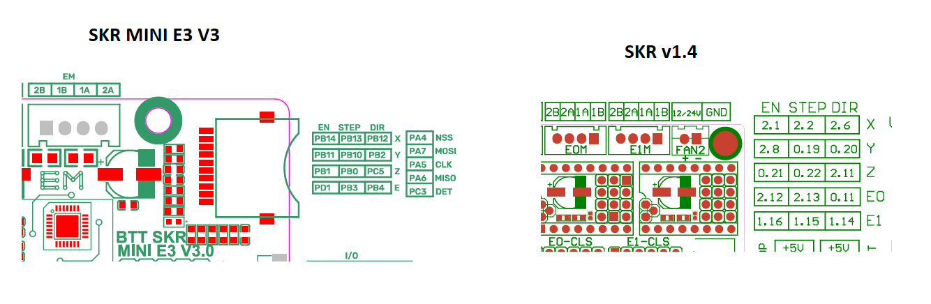
Should i rearrange the wires in the JST so that the wire that on the old card was connected to 1B, also is connected to 1B on the new card, and so on?
The EN | STOP | DIR part is in the same direction in the pinouts, even the whole connector is upside-down on the SKR MINI. Why is this? Is this just labeling the round pins?
Arrghh, I have so many noob questions…