
I’m making mechatronic Dr Octopus arms (they’re gonna be pretty sweet), and I’m in the process of prototyping the segments. They’ll be roughly 2.5 cm in height, with a 2.5 cm gap from segment to segment, and they need to be attached securely, with smooth rotation on xyz to ≈ 10°. Planning on housing the servos in the base, and running cables down the arms to actuate them. Roughly 24 segments total, with separate control cables for the first 12 and second 12 (so the first half can bend in one direction, and the second half another), along with a drive cable down the center so it can rotate on the z axis. This also means I’ll need some empty space running down the center of the segments to run the drive cable and the control cables for the second half, so they don’t impede/aren’t impacted by the bending of the first half.
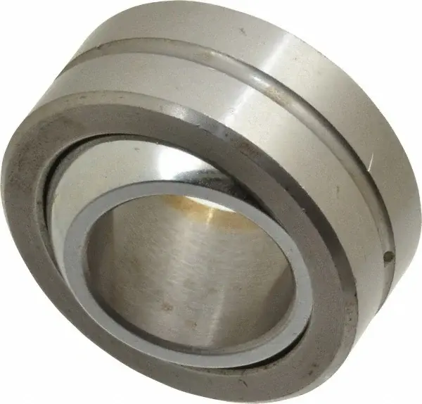
As far as I can figure, spherical bearings are my only real option here. As a test, I bought 4 steel spherical bearings from Amazon to connect the segments. And man, I love these things. I’d never handled them before, and they are smooth as butter. Unfortunately, they were like $7/per, and I need around 100 of them. So, slightly more than I’m hoping to spend haha. Aliexpress has them for ≈ $1.50/per, but the shipping is obscenely expensive, and would take like 2 months.
So I’m trying to figure out another option. I’m a member of a local maker’s space, so I have access to a bunch of tools (metal shop with lathe, CNC, FDM 3D printers), but still don’t think I have a great solution.
The tools for making these the right way are obscenely expensive. I’m thinking I could machine the race in two halves and weld/clamp them around the ball, which would be a ton of work, and wouldn’t be as smooth, but would probably be sufficient.
I could 3D print them, but I can’t figure out a process that would be as smooth as I want. They’d need to be filled/sanded, probably coated with a dry lubricant. But the filling/sanding process would introduce tolerance issues, and I can’t afford to have slop with how the cables will work.
Anyone have any insights here to help me out? Thanks!
You must log in or register to comment.
Machining matching smooth concave/convex surfaces in steel for such a bearing is fairly difficult without a precision CNC lathe, at least to get to super tight tolerances. And you definitely will not reach any level of commercial tightness/smoothness without post processing sanding/grinding or lapping. One could do it, but if you need a hundred of them, the sheer number of hours you’d need would make the Aliexpress options honestly way worth the cost.
I would revisit 3d printing them. You can probably stack about 36 of the individual parts on a typical tray, which means 2 48hr prints and youd be close to done. Use a very thin layer height- most printers can do 0.07mm.
If you want to do a 3-part bearing and assemble, overprint them by 0.020 and sand the inner and outer surfaces. print a tapered shaft that starts at -0.020in below your bearings internal diameter, and ends at +0.010in. Do the same for the external race but inverse. You should be able to simply chuck up your shaft on the lathe, slam a race on so it’s held in place, and sand using emery cloth quite quickly at a low rpm (start 180 grit, finish 360 or 400 grit). Sanding the external race may require also printing a form matching tool that you can glue emery cloth to and can match the internal bearing curve.
You might be surprised how smooth of operation you might get with a one piece print, that is, printing the captive internal race inside the external race in one go, with a thin layer height. I’ve gotten some very tight tolerances out of one piece ball joint prints when sliced and toleranced correctly. I recommend you experiment with it
I have been experimenting with the 3D printing, just not getting great results. Did a few test pieces over the weekend at 0.1 mm layers, the layer lines were still killing any kind of smooth motion I’d hoped for. Which is what got me on the fill/sand path, which is my next experiment. I’m pretty confident that with enough process experimentation, I’ll be able to get the action I’m looking for with fill->sand->possible resin coat->dry lube. Just gonna be a lot of work to get it right haha. Wish I still had access to an SLA printer; I printed out some kick-ass ball joints on a Formlab printer years ago.
The print-in-place joints, in my experience, work just great, until you try to move them while they’re loaded; ≈ 50 N*m is a lot to ask of a non-finished plastic joint lol, and that’s probably around what I’ll be working with.
print a tapered shaft that starts at -0.020in below your bearings internal diameter, and ends at +0.010in. Do the same for the external race but inverse
Could you elaborate on that? Not sure I follow.
Thanks for the help!
I’m saying make a shaft in your modelling program that is straight at the nominal dimension of your bearing race’s internal diameter such that you could slide the shaft inside the bearing inner race. But instead of being straight, taper the shaft from undersize on one end to much oversize on the other over about 3-4 inches. Profile like so. That way when you slide the race on and tap it, the taper wedges the race in place and you can quickly and easily swap parts in and out for lathe sanding. Do the inverse for the outer race- that is, make a hollow shaft where the inside tapers smaller instead of the outside tapering bigger. I do it all the time for holding handmade parts for outer sanding.
Gotcha, thanks for the wisdom!
Take a look at Igus plastic bearings. The plastic material will save weight versus steel, which you’re going to need. The price varies by size and type but should be less than what you paid on Amazon.
Your project sounds awesome! You should post pictures.
Edit: Sorry, was typing faster than I was thinking. Even if the Igus bearings are $4 each, that’s still $400 worth of parts. That seems high for a hobby project. I agree with @empireOfLove@lemmy.one, 3D printing and sanding is probably the way to go for a low-cost solution. Do you only have access to a FDM printer, or is resin printing an option?
I was just typing a response on the Igus cost haha. The size I need are only $2.50/per, still pricey, but more reasonable. I’d be more inclined to try them out if it didn’t take 30-60 days to get an order; I’d like to do a test fitting before I commit to $250 of parts, and 60-120 days is too long to wait for the full batch.
I may be able to do them in resin. My work has a whole bunch of resin printers, but this would be a lot of parts to do on machines that are supposed to be doing actual production work haha. That and the resin we use is accuracy focused, not particularly strong, they’d wear out fairly quickly.
The maker’s space recently acquired some resin printers, so might be worth it to wait until they get those operational.
Thanks for the insight!
In a complete change of direction, might it be possible to model the joints as a “bendy straw” joint and avoid this whole question of bearings?
Sure it’s possible, in fact I’m running several PTFE tubes through the center of the joints (for the drive cables and control cables) that effectively function like that. My biggest concern with this whole thing is how much it’s going to bounce around while I’m walking. I feel like a “bendy straw” will be too susceptible to shear/compression forces to give the rigidity I’m looking for.
And a hinge of some sort between the two tubes wouldn’t do it for you? You want more than one plane of movement for each segment, is it?
Yes, the joint needs to rotate on x, y, and z to about 10 degrees
