
Solution: @[email protected] has made some really insightful comments below, which are really useful. If you just want the cap you can set the parametric searches for 660uF, or in September 2023 I’ve found that digikey stock(s/ed) chemi-con EKHJ451VSN661MA59M.
Update 2: Turns out that EKHJ451VSN661MA59M is not the ordering code you’ll want. That would be EKHJ451LIN661MA59M which returns 0 results when you Google it, or maybe a single result in a few days linking to this thread. So it looks like you’d be better off just getting some 680uF with blade snapins instead and retrofitting the board if possible. Just make sure it can handle the ripple current. Always check ordering codes twice my friends!
Original post
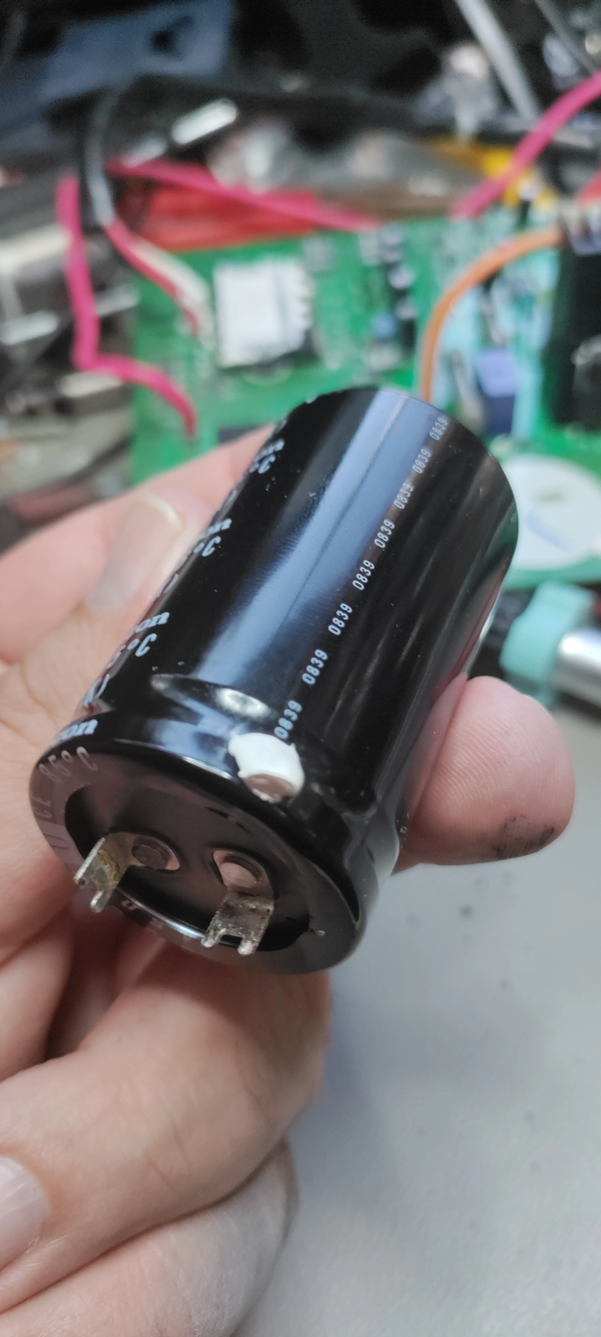
I need help identifying the terminals on some strange caps found in an AC inverter main board. The reason I state the AC part, is that the only other mention I’ve found of this layout, was a question on digikeys forum regarding an AC inverter https://forum.digikey.com/t/can-t-find-the-right-terminals-for-a-capacitor/19332 The capacitor in question has the same measurements as the one in the link.
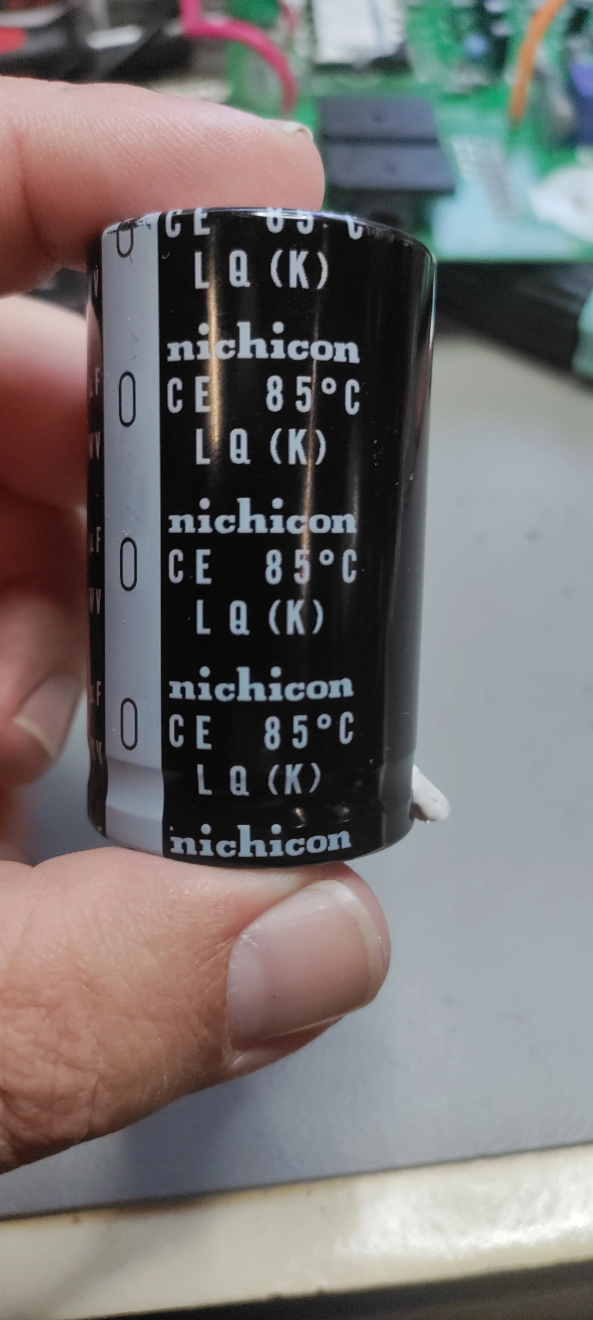
In my picture on the right you can see the layout of the terminals, there’s room for three caps, but only two was mounted, hence the relatively clean pads. On the left is one of the two caps in question. It says nichicon LQ(K), 85°C. Nichicon has discontinued the LQ-series, and the datasheet doesn’t mention a 660µF variant. I don’t know what fujitsu did to get caps with capacitance outside the E24 series.
Question: What is the name of this type of terminals? And more importantly: where can you get 680µF 450V caps with them? I haven’t found them on neither Farnell or RS-Online.
For the sake of people googling this in the future, the AC in question is a fujitsu AOYS09LDC and the board was marked K05CM-C-A(03).
Can you show more markings on the caps?
Sure, I was limited to the one in the post.
I believe this lead configuration was designed to help with vibration resistance at very low cost, negating the need for a glue down. It could also be a bit more compatible with conformal coating? I suspect they’re special order on account of the leads and maybe the dimensions (could be demanding at the time), and the space constraints didn’t really allow them to claim a full 680μF.
I’ve never tried super hard, but I’ve never manged to source these from anywhere. I think this technique has mostly been replaced by multi-lead (three to five) configurations. I don’t think I’ve seen these from anything built in the last 20 years or so. I suspect you’ll have to retrofit to get things running again.
There’s some risk but I’ve managed to make a standard snap-in capacitor work by using a pair of pliers to rotate one of the leads on it’s rivet and bending both leads for the proper angle. This doesn’t help with vibration so I’d recommend fixing it with selastic as well.
Alternately you can modify the board to fit standard capacitor leads if everything lines up ok. Don’t forget that the PTH in the mounting holes might be connecting planes on opposite sides of the board. Make some sturdy vias if necessary.
If you’re really feeling froggy you can take a page from the vintage electronic restoration handbook and (kind of) restuff the cap. It’s usually done to be pretty, but in this case you could do it without care for looks and only in order to retain the terminals. This may be unwieldy given the size. I imagine it’d essentially be cutting the base off, wiring it to the new cap, and gooping everything together neatly with silicone.
I concur on the retrofit. It’s a two layer board, and the negative and positive rails are on opposite sides. I should be able to reuse the slot for the negative rail and make a slot for the positive (bottom side) rail. That way I can still get snapin terminals, as I’m concerned about the cross section of terminals if I had to resort to some round ø1.0mm pins.
I considered the approach you suggest with turning the terminals on the rivet, but all the riveted terminals I’ve seen have been potted partly, so I’d be concerned that turning them would put stress on the rivet and internal connection. That hasn’t been an issue for you? Anyway the caps I’ve found are just short of 20€ a piece, and I’m cheap, so I don’t feel like playing around.
Restuff the caps? Has anybody ever called you a cowboy? 🤠 I guess you could do that from an aesthetic POV, and maybe with enough selastic it would work. But somewhere in the back of my mind I know that it will fail at the worst time, and I’ll have to retrofit some other caps anyway… Only this time it’ll be raining and 2°C when I have to take the inverter apart.
Thanks for the idea of retrofitting. I was so stuck sourcing a drop in replacement that I hadn’t really considered that approach. The real estate is there to take a drill press with a 1mm drill and make a slot for normal snapin connectors. It’ll even maintain the same center, somewhat at least. Time to play with some selastic!
I’d be concerned that turning them would put stress on the rivet and internal connection. That hasn’t been an issue for you?
Hasn’t come up yet in a handful of tries over the years. The clamping force in the ones I was working with was insufficient to turn the rivet when the lead was rotated so I don’t suspect damage. The potted/sealed caps wouldn’t tolerate this at all, nor would any given particularly well riveted model. I totally understand not wanting to get weird with expensive parts. The one’s I was working with were only a few USD.
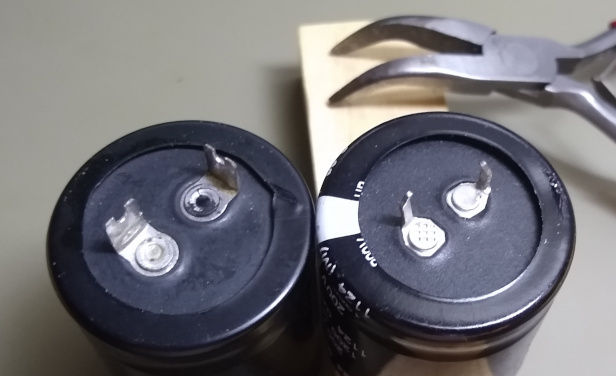
I figured I’d dig through the junk pile and see if I could demonstrate. On the left is an Elna CE-W series 470μF 200WV, Ø30mmx50mm I had lying around, probably from the late 80s/early 90s. These are likely from an old switching supply, back when they made them specifically for US 120V mains. Just included it for fun as I wasn’t sure I still had one around.
The one on the right is an unbranded 1200μF 200WV Ø30mmDx35mm with a 2011 datecode. I used the pliers in the background to give one of the leads a 90deg turn. It’s dodgy with such thin leads as these, but it can be done. Solder tie lugs are much better as they have a flat square lead shape that’s less likely to tear off. So definitely possible, but definitely dodgy.
Restuff the caps? Has anybody ever called you a cowboy?
I don’t always have the best ideas, but I do tend to have a lot of them. :)
I try to cast a wide net cause it’s not always obvious what priorities folks have in their repairs. I doubt anyone would care about the aesthetics, for sure, but you would get to do all your arts and crafts work without involving the board itself, which could make some folks nervous.
Time to play with some selastic!
If you have time for the shipping you can get some Kafuter K-704N from aliexpress et. al. pretty cheap. It’s exactly the white selastic used for electronic holddown. Also the datasheet for whichever capacitor you order should have details for the recommended board footprint and drill size so you can be sure things will line up.
Glad to help :)
Thanks for all your input, it’s been fantastic. And the ideas thing? Right there with you pal.
For future reference, I found a source for the cap. Turns out that setting your parametric filter to exactly 660uF was the trick. Found chemo-con EKHJ451VSN661MA59M on mouser with a moq of “only” 200@12€… But digikey sells them individually at the same price.